Sure, you could just replace your entire Hayward pump, but replacing only the motor is just as easy, and you don’t have to touch any of the plumbing. Plus, you can save $100 or more.
In case you need to know, a pool pump motor is the rear-half of the pump, the black metal cylinder, or for original Hayward pumps, a motor painted in a bright gold color.
The plastic front-half of the pump, known as the ‘wet end’ of a pool or spa pump, can last for decades with a few new pump parts; mainly gaskets, baskets and lids.
Hayward pump motors last 8-10 years, if you’re lucky – but when they begin to overheat and shut down, or when the bearings begin to squeal, or if your motor trips the circuit breaker, it may be time for a new motor.
HAYWARD PUMP MOTOR SELECTION
- Match the motor Horsepower (HP), and Full Rated or Max Rated (Up Rated)
Hayward pumps with an “X” in the Model # use Max-Rated motors
Max-Rated motors will have a lower listed Service Factor (SF) - Match the motor Speed; single speed, dual or variable
- Match the motor Frame (FR) Type
Max-Flo, Superpump and Super II pumps use 56J Frame ‘Round’ Flange
Max-Flo II, XL and TriStar use 48Y Frame ‘Square’ Flange motors
PowerFlo LX, II and Matrix use 48 Frame ‘Thru-Bolt’ motors
Northstar pumps use a ‘Special’ 56J Frame ‘Round’ Flange motor

HAYWARD SHAFT SEAL SELECTION
The mechanical shaft seal prevents water from leaking along the shaft, a simple 2-piece device that seals tight around a steel shaft rotating at 3450 RPM.

Hayward uses different shaft seals depending on the motor that is used, but also to match different pump seal plates. Be sure to use the correct seal, and take care to install the new seal halves in the same orientation as removed, facing each other correctly, as shown in this picture.
- MaxFlo, Superpump and Super II pumps use seal SPX1600Z2 or AS201
- MaxFlo II, XL and VS and Booster pumps use seal SPX2700SA or AS200
- EcoStar, TriStar and NorthStar pumps use seal SPX3200SA or PS4280
- PowerFlo LX, II and Matrix pumps use seal SPX1500KA or generic AS4702

Or you could just use the “Go-Kit” made for your particular Hayward pump. Pump rebuild kits that contain all of the o-rings, gaskets, seals used on your specific Hayward pump, plus Teflon lubricant.
Hayward pump o-ring kits are available for MaxFlo, PowerFlo, Super Pump, Super II and NorthStar pumps.
HAYWARD PUMP MOTOR REPLACEMENT
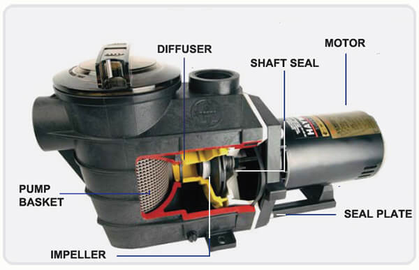
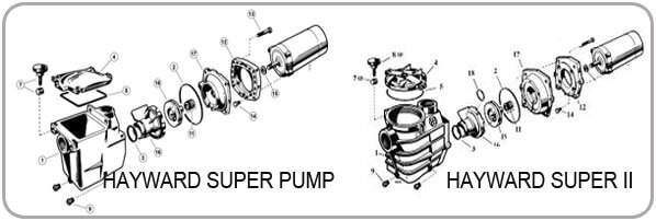
Our schematic diagrams of Hayward pool pumps can be very helpful to look at during a motor replacement – to see how all the bits fit together, and for help in naming the various parts that connect to the motor.
Replacing a Hayward pump motor is no different than replacing a Pentair or any other brand pump motor – it’s basically dis-assembly and re-assembly.
Hayward Inground Pump Motor Installation
1. Obtain your materials: You will need a pool pump motor of course. It must be the same horsepower (hp) as your previous one, to match up correctly to the hp-rated impeller. You will also want to replace the mechanical shaft seal. You can buy the seal separately, or you can purchase a GO-KIT which contains all of the gaskets, seal and o-rings for a particular pool pump. You need not replace all the gaskets or o-rings when you replace a motor, unless they are suffering from dry-rot. If the rubber o-rings look good, just use some magic lube or other silicone based lubricant.
2. Pull the Motor: Shut the power off at the circuit breaker. If your system is below water level, close incoming valves. Usually there is a clamp band that connects the seal plate (the plate that the seal fits into) to the volute, or impeller housing. Sometimes, the seal plate is connected to the volute with 4 or 6 bolts, as is the case for the Superpump shown above. When pulling a motor out of the housing or volute, the motor will remove with a seal plate attached. You may need to pry gently with a flat head screwdriver to separate the two halves, after removing the clamp or the bolts. Grab the motor firmly and pull it straight back.
3. Remove the Wiring: Most pumps will have three wires. For a 220V motor, both black and white (or red) wires will be “hot” – so make sure that the power is off at the breaker. There will also be a green ground wire connected to green screw head. Remove all 3 wires, and remove the conduit connector from the old motor and screw it in the same place on the new motor. If you have a two speed motor, you will have a 4th wire, the low speed wire. If you have 4 wires, you may want to label them as you remove them.
4. Remove the Diffuser: Also known as an impeller shroud, or # 18 in the picture above. Sometimes these simply pull off, and sometimes screw removal is required. Remove and set aside, keeping tabs on the diffuser gasket, #3 in the picture above.
5. Remove the Impeller: The trick here is to secure the shaft of the motor, so that you can spin off the impeller. It is regular threaded, counter-clockwise to remove. If you have an older pump, with an open bracket, where you can see the shaft, then you can grab the shaft at this point, with vice grips or channel locks, hold it tight, while spinning off the impeller. Most modern pumps now have no access to the shaft, so in most cases, the easiest way to secure the shaft is to open up the back of the motor, loosen the capacitor (black cylinder) so you can move it out of the way, and put a 1/2″ open end wrench on the end of the shaft. You will find the shaft slotted to accept the wrench. The centrifugal switch will be on the end of the shaft, you will be inserting the wrench behind the switch, and then simply propping the wrench handle up against the motor body to hold the shaft stationary, while you grab the impeller firmly and turn counter-clockwise to remove. If too difficult to remove by hand, use large channel locks to gently remove. Too much pressure and you may crack the impeller. A strap wrench is a useful tool for impeller removal, but the key is to secure the shaft.
A few pumps have a reverse threaded impeller screw (Challenger, Hydro). After pulling the pump, look into the center of the impeller. If you see a screw head, use a good fit screwdriver to remove the reverse threaded screw, clockwise. These are often made of brass, which has softened over time, so to avoid damaging the screw, use a screwdriver that fits the screw head properly.
6. Remove the Seal Plate: You will find 4 bolts to remove the seal plate from the motor. After the bolts are removed you may need to pry or hammer slightly to remove the plate.Remove the seal half or “donut” portion of the shaft seal in the center of the plate.
7. Install the Seal Plate: Onto the new motor, bolt the seal plate with the “donut” half of the shaft seal firmly pressed into the seal plate, in the same orientation as the old seal half removed from the seal plate. Be careful not to touch the ceramic face with greasy hands or allow the seal half to become scratched. If it’s too tight to push in by hand, use a small piece of 1″ pipe, with a shim of light cardboard to press fit the seal into place. A rubber lubricant can be used, or you can use a little bit of saliva to lubricate.
8. Install the Impeller: Much easier this time. Just thread it on. But first you will need to replace the half of the seal which has the spring. Make sure it goes on correctly – one side has a soft rubber and one side has a harder plastic. The plastic side faces the ceramic donut half of the seal and the rubber side faces front, toward the impeller. If your impeller has an impeller screw – replace after spinning the impeller on all the way onto the shaft. If your pump uses what is called a “keyed shaft” motor, then you will have a brass stub shaft that will fit over the keyed shaft. After threading the impeller onto the stub shaft, you will align the impeller very close to the seal plate, and then tighten up the set screws which hold the stub shaft onto the keyed shaft.
Before re-inserting the motor into the pump, make sure to replace the diffuser over the impeller (I always forget this step!). Be sure the diffuser gasket or o-ring is in place before sliding motor back into the pump housing.
9. Replace the Motor into the Housing: Clamp it together making sure the seal plate is making good contact all the way around. Lubricating the seal plate o-ring will help ensure a good fit. Lubrication can also help to hold the o-ring in its groove as you position the two pump halves together. On some Sta-Rite and Pac-Fab pumps this can be very helpful. Get your bolts tightened up snug, but no need to put 100 lbs of torque on them. Same thing with the clamp band. Tight, but not overly tight. Tapping a clamp band around it’s edges as you tighten can make for a better fit.
10. Replace the Wiring: Your new motor will come wired for 230V. This is to prevent the damage of hooking up 230V into a motor that is wired for 115V. If you do have 115V powering your pump (one that plugs in to an outlet, or is connected to a 115V timeclock) then you will follow the wiring diagram on the motor label. This label will guide you to reversing the voltage, or changing the voltage from 230V to 115V. Larger motors will be reversible (115 or 230) or they will be 230V only.
If you are 230V – then simply run the wires through the conduit connector that you screwed onto the new motor, and connect the ground wire to the green screw. Then put your two hot wires onto the two terminals. It doesn’t matter which wire goes to which terminal. make sure that your wires are not touching each other, or the sides of the motor. Strip new wire ends if needed, inspecting the wires for bare spots or deteriorated casings. Tighten down the wire connections firmly, and replace the motor end cap, being careful not to pinch wires.
Hayward Above Ground Pump Motor Installation

Replacing a Hayward aboveground motor is essentially the same, but there are some unique differences when installing a new Hayward PowerFlo motor.
- Shut off power at the circuit breaker, or just unplug the pump from the outlet.
- Remove the rear cover plate to expose the power wires. Disconnect the incoming ground wire and two power wires from the terminal board.
- Using a screwdriver, loosen the cable clamp, pull on the power cord to gently remove the wires and cord out of the old motor.
- Remove the C-clip to separate the pump pot from the pump volute or impeller housing. The clip for PowerFlo Matrix is internal, inside the strainer housing, remove the basket to access. PowerFlo, LX and II have an external clip, between the strainer and volute.
- Remove the drain plug or lid to empty the PowerFlo of water. Remove the housing bolts to separate the pump housing from the housing cover to expose the impeller. Rotate the strainer housing or pump as needed for bolt access.
- Hold a large flathead screwdriver on the slotted end of the motor shaft at the rear of the motor to hold the shaft stationary, while you spin-off the impeller (CCW) by hand. Sticky impellers may require channel pliers or a strap wrench to remove.
- Using a 1/4″ socket or nut driver, loosen the 4 thru-bolts at the rear of the motor and remove the pump housing from the old motor.
- Reverse! Secure the pump housing to the new motor, with the two halves of your new shaft seal, placed in the same orientation and then spin-on the impeller by hand.
- Clean, inspect and lube the housing o-ring, strainer o-ring and strainer cover o-ring, replace if needed.
- Replace the housing bolts to tighten the housing cover and replace the C-clip. Reattach the power cord, fill the pump with water and you are ready to rock!
Hayward Pump Motor Replacement Video #1 Disassembly
Hayward Pump Motor Replacement Video #2 Reassembly
Other Hayward Motor Replacement Tips
- Use the proper size tools – screwdrivers, wrenches, nut drivers and pliers.
- Use a good pool lubricant, Teflon-based lube for pool o-rings.
- Spray PowerFlo thru-bolt threads with WD-40 before loosening.
- Place the shaft seal in the same orientation, if backwards it will leak!


What if any is the difference between the black 1.5 hp super pump and the gold one? And does it even matter?
Hi Mike – the gold color motors are made by AO smith for Hayward, and painted gold. But the motor is no different than one painted black. So, no difference other than color (I like the Gold!)
I changed the seal in my Purex Triton pump. The pressure reading went from 20 to about 11 and the flow is not as strong. What may be causing this?
Hi Coby, assuming that the new seal is not leaking water… it likely is not the cause. Is it possible that the impeller is clogged? Is there an air leak, drawing air into the pump? Are some incoming valves partially closed? Is the pool water level correct?