 Second in our Series of Gas Pool Heater Troubleshooting Guides, today we tackle the early electronic pool heaters from the mid-eighties to the late nineties.
A Spark Ignition is akin to an electronic gas stove top. When your turn on a gas burner on a stove, you don’t have a pilot burning, you have a sparker (tick-tick-tick) that lights one side of the burner, and then the burner orifices quickly ignites, all around the burner. Gas hot water heaters work the same way.
This new generation of gas pool heaters is a whole new ball game. Gone is the pilot generator and mechanical thermostat. Electronic heaters are wired up with 110V or 220V power directly into a transformer, which steps down the power to 24V. From the transformer, 24 volts powers the entire ignition and safety circuitry, and everything is controlled electronically with the Ignition Control (PCB, printed circuit board), the brains of the operation.
But, aside from the IID controller, transformer, a redesigned electronic thermostat, gas valve and pilot, electronic heaters still function in the same way as millivolt heaters. Once the safety circuitry checks out, the gas valve opens and releases gas to the burners. The pilot light ignites the first burner (on the far right), and the others follow – whoosh!
After a heater ignites, it continues to fire or burn until the set thermostat temperature is reached, or another switch breaks the circuit (pressure switch, high limit switch, on/off switch).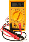
You’ll need a multi-meter, one that can check low voltage 24 Volts. You can find these everywhere – Walmart, Home Depot, Radio Shack, and it should cost under $20. You don’t need a fancy test meter to troubleshoot a pool heater.
ELECTRONIC POOL HEATER TROUBLESHOOTING GUIDES
For our example heater, we will be using the Old Teledyne Laars Series I & Series II Spark Ignition heaters, made from 1986-1997; but the concepts apply to electronic heaters made by Raypak, Hayward or Purex – RP2100, H-Series or Minimax Plus heaters.
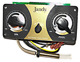
The diagram below is from the Teledyne Laars Series One heater, Model EPS/EPC, and Laars Series 2 ESC. The Dual thermostats (shown above) is something of a gimmick, it just allows you to keep two preset temperatures, and use the 3-position Spa-Off-Pool switch to select Spa or Pool, it’s nothing more than that. If fact, if your Pool Thermostat (potentiometer) wears out, you can use the Spa thermostat to heat the pool.
What we have here is a schematic diagram of the safety circuit in an electronic gas pool heater. The Transformer (1) steps down the incoming power to 24 volts, and the power does a circuit, or a loop, from one side of the gas valve to the other.
When the power successfully passes through all of the components (fuse, fusible link, high limits, pressure switch, thermistor) and again returns to the Ignition Controller (6), the gas valve (8) should open and allow gas to flow into the pilot, which is lit by a small spark (7A), created by the spark ignition wire. The pilot (7B) is lit temporarily, which lights up the burners. Whooosh!
Let’s take it step by step…
STEP 1: TRANSFORMER CHECK
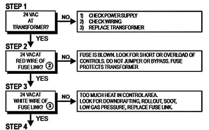
If your heater has no power at all, check the circuit breaker or look for a popped GFCI outlet. Next, verify that you have 24 volts coming in and out of the transformer. Place your test meter on VAC (AC Volts), on a low scale 100 or 200 volts. Then place each probe onto the metal spade connectors of the transformer to verify 22-26 volts, no more – no less.
Inspect the wires too, looking for any obvious signs of damage from heat or rodents. If you don’t get 24 volts on the transformer, Replace the transformer (pn R0061100), they go bad every once in a while.
STEP 2 & 3: FUSIBLE LINK CHECKS
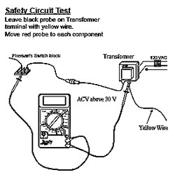
With the Black, or Common lead from your multimeter remaining on the Yellow Wire side of the Transformer, you will move the other Red lead around to different heater components, starting with the Fusible link, a small white part that sits down near the burners, to sense flame rollout. Move your Red meter lead to both sides of the Fusible Link. If you find power coming in (2), but not coming out (3), you either have a bad In-line Fuse (pn 10480000) or a bad Fusible Link (pn R0012200).
The cause of a failed Fusible Link should be investigated. It could be material laying on the burners, or leaves or nests on top of the heat exchanger, or high winds downdrafting, or soot or lime deposits between the copper heat exchanger fins.
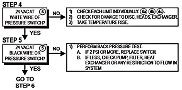
STEP 4 & 5: PRESSURE SWITCH / HIGH LIMIT CHECKS
Keeping the black wire on the transformer (an alligator clip adapter for a test probe is useful), move to the probe to the pressure switch (R0011300) and check for 24 volts on each pressure switch spade terminal. Be sure you are contacting the brass metal of the terminal. If no power is found coming into the pressure switch, back-up and test each Hi-Limit (4B 4C) and the Fireman’s Switch terminal (which shuts the heater off 15 minutes before the pump timer is going to shut off, for a cool down period). Remember – the problem lies where the power dies!
If the Hi-Limits (R0023200 and R0022700) are tripping, or the cause of the problem, check the Internal Bypass assembly (pn R0054900), in the front header, for broken, missing or misaligned parts. A temperature rise can be done with a special thermometer inserted into the drain plug hole (pn R0336000), to see how high the temperature is rising inside of the header.
If you find no voltage or less than 24 volts on the black wire (outgoing) of the pressure switch, check for a dirty filter, dirty pump or skimmer baskets or closed or partially closed valves or broken check valves. Also check for an external bypass, a valve outside of the heater, which can allow too much water to bypass the heater.
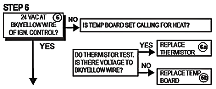
STEP 6: THERMOSTAT CHECKS
On this step just move your Red lead over to the black/yellow striped wire on the Ignition Control box, to the terminal labeled 24V. Again be sure to contact the metal spade connector on the Controller, without removing the wire, although you can loosen the wire if needed. Turn the thermostat up, and the On/Off switch towards the correct dial.
If there is not 24V at this terminal, replace the Temperature Board (pn R0011700) and if there is 24V but no heat, it’s most likely the Thermistor (pn R0011800).
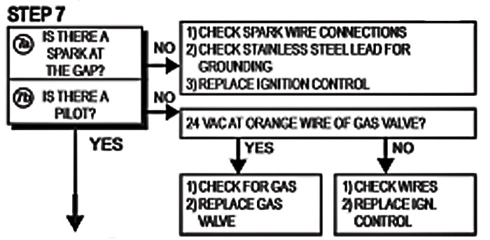
STEP 7: SPARK CHECK
For Step 7A, Check if there is a Spark at the Gap, by removing the Spark Ignition Wire, pulling back the rubber boot and holding it close to the connector. With thermostat turned up, the call for heat should be sending a small, visible electric spark, jumping the gap from the end of the rubber coated wire, to the connector. If no spark, check the stainless steel wire that runs from the Ceramic Insulator to the Pilot (R0099000), to be sure the power is not grounding out to the burner tray, or some other metal piece. Also check and clean where the SS wire connects at the bottom of the pilot. Make a Visual Check of the Position of the pilot and sparker, to be sure there aren’t nests or insects or debris, and it all appears intact. If you have followed the steps to this point and have 24V up to the Spark Ignition Wire, but no spark jumping the gap, the problem may be the Ignition Control Box or IID (Intermittent Ignition Device) (R0011900).
Step 7B, the pilot (7B) lights, but you have no ignition or firing of the heater burners; use your multi-meter in the same settings and position as used above, check for 24V at the Orange Wire on the Gas Valve. If Yes, check for clogs in the pilot or burner orifices, or in the gas supply. You may also suspect the volume and pressure of gas supply at this point, Propane tanks could be low, or other high demand natural gas appliances could be in use. First consider and check the wires, looking for sharp bends or nicks in the wire casing, and making sure wire nuts, screw or connectors are clean (not rusted) and tight. If damage is found, replace Wire Harness (pn R0058100), and possibly the Ignition Controller still could be the problem. Circuit boards in the good old outdoors tend to fail in 8-10 yrs.
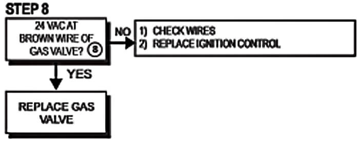
STEP 8: GAS VALVE CHECK
If you have come this far, with a pilot burning and 24V at the Orange wire on the Gas Valve, now check for 24V on the Brown wire on the gas valve. If no, your brown wire is highly suspect, or the circuit board (Ignition Control) is shot. If you do have power, at 24V (or at least 22V) at the Brown wire and the heater won’t fire – give the gas valve a little tap with a hammer (really!). If it still won’t fire off, the electronics inside the valve have failed, replace the gas valve, (R0095900 and Nat pn R0099400). Check for a clogged intake screen as you remove it.
Before you go and throw down several hundred dollars on a new Gas Valve or Ignition Control – go through the steps another time to be sure – I’d hate to waste your time and money, buying pool heater parts that don’t fix the problem!
And…These part numbers I’m throwing around Fit only Jandy (Laars) Series 2 ESC heaters, be sure to check your model size, some don’t fit other models!
After running through all of the steps at least twice – if you want some confirmation of your Laars heater troubleshooting, you can call us at 877-766-5287 (1-877-POOLCTR), to speak with a pool tech, who can answer any questions on the process. Jandy Laars (Owned by Zodiac) also has homeowner technical support, and heater manuals online, or call them at 800-227-1442.
Oh, I almost forgot – here’s the link for over 150 gas pool heater parts schematics! Support your local swimming pool blog!
Thanks for Reading!

Mark Garcia

Mark. My Hayward H350 fires up but… as soon as the igniter stops ticking it shuts off. It goes on and off this way for several cycles and then I either get a “LO” or “IF” error.
Any ideas what could be causing this?
Hi lou, the most common IF (ignition failure) problem is usually low gas pressure. LO may mean low gas or low flow. Some larger LPG heaters won’t fire reliably when the tank gets below half empty. Or if not a gas pressure issue (or clogged burner orifices), then it could be an ignitor failure.
I have a Teledyne Laars Series 2 I would like to know if besides gas which is installed they need any type of electricity to be done in order the heater will work in my pool, I’m confused cause they told me yes in the beginning and now they no?
Millivolt heaters do not need an external electric connection, but the early electro-mechanical and today’s digital heaters do require a power connection. If your heater has a transformer and an IID box, a grey ‘Fenwal’ or other ignition control box, then it would need power, from a breaker or jumped off an electrical outlet. I may be mistaken, but the Series 2 ESC and ESG models are both millivolt, requiring no hookup.
Mark, I have replaced the temperature control board on my Laars series one pool heater due to both thermostats wearing out. They now work but my heater continues to cycle as thought there is not enough pressure. How can I tell if I need to replace the pressure switch? Could there be another component failure that could cause this?
Louis, the automatic bypass assembly can affect pressure and flow, it is located in the front header, where the pipes are attached, and allows water to bypass the heat exchanger and bypass into the exit side of the front header or manifold. There is an access plate on the side of the front header, for the purpose of inspecting the assembly.
Hello, I have a Laars series one heater. On the Temp control panel there’s three setting, Spa,Off,Pool. When I turn the setting to pool no problem, but when turning to spa it will ignite and a few seconds later it kick off. I found that if I hold the switch for a few minute than it will stay on. Do you know what I should do.
The dual thermostat allows you to keep two temperature settings, locked-in, without having to turn the dial for spa or pool temperature levels. It’s nothing more than that – just two separate thermostats. When one works and the other doesn’t, just use the one that works. In your case, it sounds like a loose connection on the switch, or perhaps some corrosion, or a crimped or damaged wire, or it could indicate some near failure with the spa thermostat or potentiometer.