Today we begin a new series of ‘Explainer Posts’, designed to enlighten our readership on the inner workings of pool equipment. The heart of the your pool circulation system, your pool pump is called to perform continuous duty, every day of the pool season. And like your precious heart, keeping your pool pump working is the most important part of pool maintenance. When the pump is not working, ain’t nothin’ workin – and this needs to be fixed fast.
Knowing the components of your pool pump, as well as a general understanding of how the pump and motor operates, can be very helpful in a quick diagnosis and repair.
LID ASSEMBLY
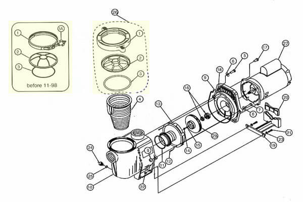
The lid assembly, includes the lid (or cover), lid o-ring and clamp. Several modern pumps use the Cam & Ramp style of 1/4-turn locking lid shown above (1), which replaced the steel clamp band (1) shown upper left, which replaced dual knobs used on many older pumps.
Common problems include damaged o-rings, cracked pump lids or faulty clamp bands or just loose lids. The pump lid must be very tight to create an air-tight seal.
TIP: Use a Teflon based pool lube on the pump lid o-ring to help seal and protect.
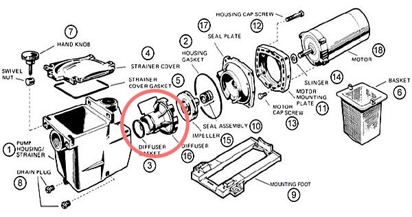
PUMP VOLUTE
The pump Volute could also be called the Impeller Housing, but that’s a bit of a misnomer, as the volute really handles the volume of water leaving the impeller. The Volute (8) is connected between the Hair & Lint Pot and the Seal Plate, but some pumps like the Whisperflo and Superpump for example, have a one-piece Volute/Strainer.
Common problems include cracking from freeze damage or plumbing damage. Not usually a common replacement part, but can be replaced fairly easily if needed.
HAIR & LINT POT
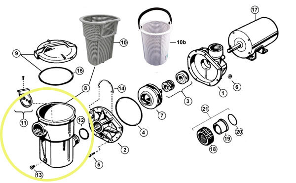
Some pumps have a Strainer Pot, aka Hair & Lint basket assembly that is separate from the Volute. On larger commercial pumps, the assembly is always separate, as the baskets can reach 12″ in diameter. For residential pumps, the pump basket diameters are usually 6″.
Common problems include cracked baskets or cracking from freeze damage or plumbing damage. Not usually a common replacement part, but the Strainer can be replaced if needed. Power-Flo’s check-valve (11) can become damaged. Missing drain plugs (13), or bad pump lid o-rings.
TIP: Cracks around the inlet port can be fixed by tightening a fitting into the port until the crack widens then clean with pipe cleaner. Fill crack with ABS glue and quickly unthread fitting to seal.
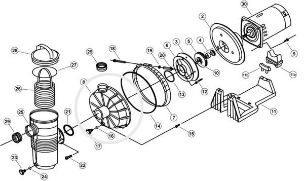
DIFFUSER
The Diffuser (16) encloses the impeller, to focus the draw of water into the impeller eye, and control the flow out of the impeller with a series of stationary vanes. The Diffuser seals the impeller eye up to the back of the Pump Housing (1), to create suction.
Common problems include a missing or damaged Diffuser Gasket (3) or O-ring, an oh-so important part to your pool pump. Sometimes they fall off the front end of the Diffuser, when removing the motor for service.
TIP: If the Diffuser does not tighten down fully over the impeller, the impeller may not be fully seated.
IMPELLER
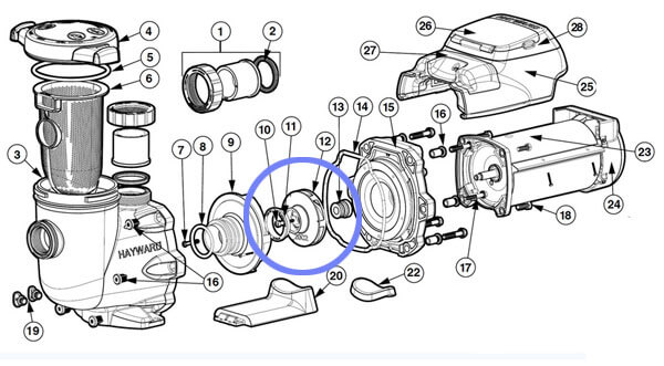
The Impeller (12) is a rotor used to increase the pressure of the pool water. The opposite of a turbine, which uses the water flow to create energy, an impeller uses energy to create water flow.
Common problems include clogging with fine debris like grass clippings, pine needles, pebbles, seeds or the stamens from flowering trees. Reach into the eye with needle nose pliers, or remove the motor and ream the impeller vanes with a small wire.
Impeller wear rings are small plastic rings (10) that protect a misaligned impeller from rubbing, and must be installed before placing the Diffuser.
TIP: Each horsepower motor is matched to a slightly different sized impeller, with a different part number.
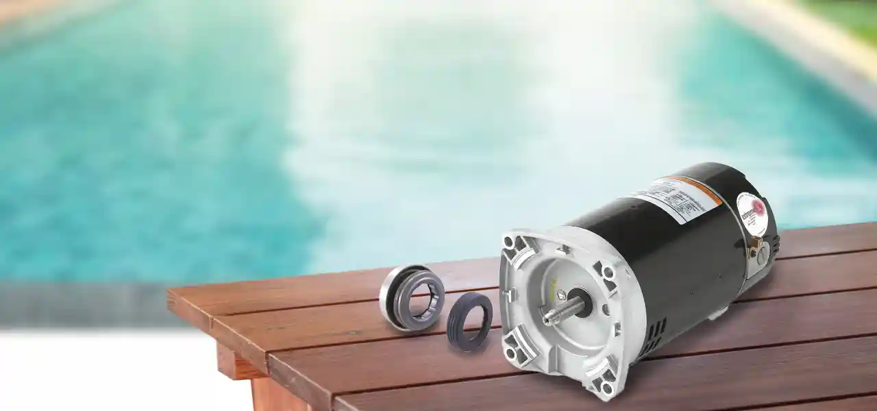
SHAFT SEAL
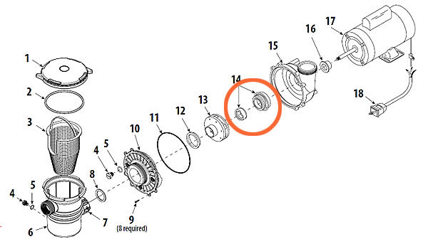
A shaft seal (14), located behind the impeller, is an ingenious two-piece device that allows the motor shaft to pass through the seal plate, spin at nearly 3500 RPM, and not leak water along the shaft, protecting the motor and preventing leaks.
Common problems include leaking and failure due to high heat, poor water chemistry, salt or ozone corrosion, or water-hammer damage. Shaft Seals are inexpensive, but only one size fits your particular pump. Most pumps use seal #100, #200, #201 or #1000 seals.
TIP: The shaft seal only can be installed in one correct manner. Counter-intuitively, the soft rubber side of the larger ‘spring-half’ of the shaft seal goes toward the impeller, and the hard plastic side faces the motor.
SEAL PLATE
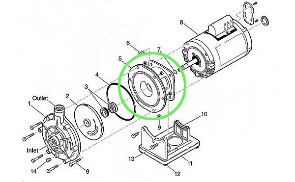
The Seal Plate (5) and a Bracket in this case, is what is attached to the motor, behind the impeller (2). It is called a seal plate not because it seals up to the pump volute, which it does, but because it provides a place to install the back-half of the shaft seal (3), the ceramic ring installed in the center of the Seal Plate.
Common problems are not common with a Seal Plate, but older Polaris booster pumps as shown above may experience small stress fractures around the seal seat, which requires replacement.
TIP: Use a Teflon based Pool Lube to help hold the Seal Plate O-ring in place when replacing a motor assembly back into the pool pump.
MOTOR
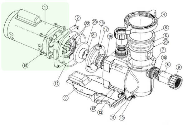
The Motor (1) is electrically driven, and the power causes the rotor to spin as the electromagnetic poles alternatively attract and repel each other. The motor is connected to the impeller (21), and when fed an air-tight supply of water, will create pressure and water flow. New style variable speed motors permanent magnet motor, which run cooler and quieter and with longer lifespan than their less efficient induction motors, used on standard pumps.
Common problems include overheating, shorting of the windings, hot spots, water damage. Most pool pump motors last around 8 years, or longer if you’re lucky.
TIP: For areas with heavy rain or strong sunshine on the pump area, consider a vented Motor Cover to protect the motor.
VARIABLE SPEED DRIVE
For those of you with the Variable Speed pump, a Variable frequency drive (VFD) is what is used to vary the frequency and voltage of power supply. The VFD also controls ramp-up and ramp-down of the motor during modes or programs. This is essentially the ‘hump’ that sits atop the rear of the VS pump motor.
Common problems include problems with the control assembly (23) or motor drive (25), or a new control or wiring covers. Before buying, run through the complete diagnostic in the owner’s manual, and contact the pump manufacturer to verify the diagnosis.
TIP: For problems with your VFD, contact the manufacturer as it may be covered under warranty.
WIRE HARNESS
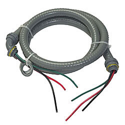
The Wire Harness is a name for the pump power wires and conduit, along with the conduit connector fittings. The entire assembly of 3 wires, flexible conduit and connectors is called a ‘wire whip’ by some pool guys.
Common problems include cracked conduit or wires, or loose connectors, especially after 20 or 30 years. If your pump wire whip needs to be replaced to lock out moisture and wet fingers, it’s an easy project that won’t cost much money or time to correct.
TIP: Buy a 12/3 Wire Whip Kit with 3/4″ conduit/connectors, in the length needed to reach your timer or switch box.


I get blowback from pump to skimmer
This just started.
Hi Jerry, that would be an air leak, on the suction-side, before the impeller. Most likely from the pump lid, the pump drain plug or the pipe that threads into the pump.
Hi Davy, I have an intex 15 x 48 metal frame pool. I purchased a hayward ec40 d.e filter/ pump combo. Based on info from this site. Super excited it finally came in! However, the new system uses 1.5 hoses and the current is 1.25.i bought the hose b adapters but they’re threaded. What else do I need in order to convert? It seems those adapters aren’t enough. I’ve searched your blogs and all I can find is that all I will need are those adapters. Please tell me what I am missing. Thank you in advance!
Hi Meghan, sorry for the confusion, the Type B adapters are for intex hoses. We have another adapter that you would put on the pump and filter, to use the Intex Hoses that came with your pool. Found here: https://www.intheswim.com/p/game-intex-bestway-hose-adapter-kit-for-softsided-pools-4560